
EPIC CONSTRUCTION MANAGEMENT LLC
Building today for tomorrow.
- SUPPORTING DETAIL
Capacity and Service Framework
A 24 MW mixed-workload example
This example allocates 24 MW of IT capacity across four workload groups. Rack counts are capacity arithmetic for coordination; they are not a verified floor plan, an equipment order or a server count.
Source basis: September 9, 2026 planning package · Not independently re-underwritten.
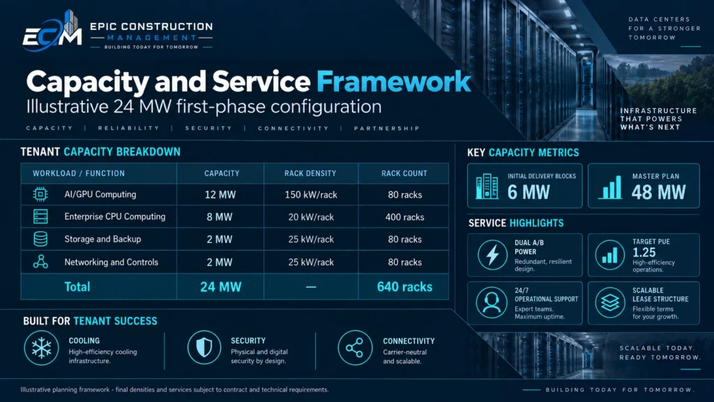
- ILLUSTRATIVE MIX: 640 is a rack-position example, not the number of servers. Equipment, floor layout, power and service terms remain to be validated.
24 MW
Total example IT capacity
640
Illustrative rack positions
150 kW
AI-rack planning envelope
Planning data & boundaries
| Workload | IT allocation | Planning density | Rack positions |
|---|---|---|---|
AI / GPU computing |
12 MW |
150 kW / rack |
80 |
Enterprise CPU computing |
8 MW |
20 kW / rack |
400 |
Storage / backup |
2 MW |
25 kW / rack |
80 |
Networking / control |
2 MW |
25 kW / rack |
80 |
TOTAL |
24 MW |
Mixed density |
640 |
How the rack arithmetic works
Rack positions equal allocated IT kilowatts divided by the planning kilowatts per rack. For example, 12,000 kW divided by 150 kW produces 80 AI rack positions. These are density envelopes, not guarantees about usable floor space or installed equipment power.
Racks, servers and GPUs are different measures
The number and type of servers inside each rack depend on the selected equipment. Rev B contains a specific hardware example, not a permanent equipment choice for a facility opening years later. Do not call a GPU count a server count. No hardware procurement is authorized or priced here.
Facility design interfaces
Validate point and rolling loads, full coolant-filled mass, rigging paths, clearances, rack connections, busway, coolant distribution and residual air cooling. Reconcile in-rack and shared network/control loads so the same power is not counted twice.
Ownership and recovery
The working boundary places building, electrical/UPS, heat rejection, physical security and facility controls with the facility entity. Tenant compute, storage, active fabric, software and customer backups remain separate unless agreed otherwise. Local storage capacity does not establish off-site recovery.
Source trail
- Rev B model: IT_Plan; Interior_BOD; Recovery.
- Original prospectus: slides 10, 18.
- Original document names and publication boundaries are listed in the source register.