
EPIC CONSTRUCTION MANAGEMENT LLC
Building today for tomorrow.
- SUPPORTING DETAIL
Core Infrastructure Scope
Work-package interfaces and delivery controls
The cutaway is an illustrative systems diagram. It helps organize trade scopes, ownership and testing, but does not specify the final architecture, equipment locations, service voltage, cooling topology or code compliance of a selected site.
Source basis: September 9, 2026 planning package · Not independently re-underwritten.
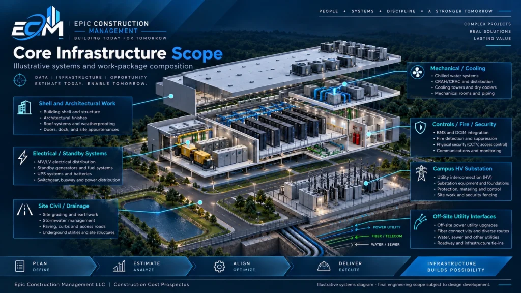
- ILLUSTRATIVE SYSTEMS DIAGRAM: Not an engineered layout, equipment specification, approval or evidence that service interfaces are secured.
7
Core package interfaces
Independent
Commissioning workstream
Site-specific
Approvals and final engineering
Planning data & boundaries
| Work package | Proposed scope boundary | Key interface |
|---|---|---|
Site civil / drainage |
Earthwork, roads, drainage, underground services |
Parcel hydrology, utilities and equipment-yard access |
Shell / architectural |
Structure, enclosure, roofing, doors and support spaces |
Tenant loads, maintainability, fire/smoke and security assemblies |
Electrical / standby |
MV/LV distribution, UPS, standby fuel, switchgear and busway |
Utility protection, cooling/controls loads and tenant rack connections |
Mechanical / cooling |
Heat collection, distribution, rejection and support HVAC |
Tenant/CDU demarcation, water, residual air and redundancy |
Controls / fire / security |
Facility monitoring, detection/suppression and access |
Operator duties, tenant IT boundary and integrated controls |
Campus HV substation |
Foundations, equipment, protection and metering |
Utility / owner scope, corridors, voltage and energization |
Off-site interfaces |
Grid, diverse fiber, water/sewer and road tie-ins |
Service agreements, easements, capacity and permits |
Define the interfaces before buying equipment
Use one responsibility matrix to separate utility work, owner work, trade scope, facility controls and tenant equipment. Confirm who supplies rack CDUs, busways, connections, controls integration, testing and spares. The illustration does not prove that different vendor systems will work together.
Procurement and live-phase construction
Prioritize the actual utility path and long-lead equipment only after adequate technical/commercial gates. Preserve cancellation controls and allocate escalation and delay risk. Phase 2 work requires safe physical and operational separation from live Phase 1 power, cooling, access and security.
Commissioning and turnover
The proposed sequence is design review, factory acceptance, receipt checks, installation and prefunctional checks, energized/integrated tests, then operator and tenant acceptance. Include approved failure scenarios, defect closure, training, emergency procedures, spares and record documents. Physical completion alone is not ready-for-service.
Permit, noise and safety scope
Build the actual municipal, county/regional, Illinois and federal applicability register for the parcel and operating modes. Separately evaluate fuel/battery hazards, emissions, water, noise, utility obligations and worker safety. The engineering teams and authorities must establish the final requirements; the illustration is not permit evidence.
Source trail
- Original prospectus: slides 12-16, 23-34, 39-40.
- Rev B model: Interior_BOD; Site_Utility; Budget_Boundaries.
- Original document names and publication boundaries are listed in the source register.